![]()
![]()
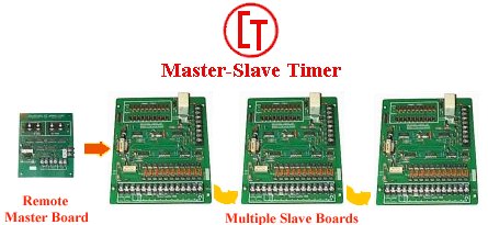
The Master-Slave timer was designed to allow multiple slave boards to be controlled by a master timing board. A system designed by Collectrol Timers Inc.
![]()
The master board has two digitally set timing circuits to generate ON and OFF timing periods. Each period is set by thumbwheel switches from 00 to 99 in a single digit steps. The ON TIME is set in half AC line period steps of 8.333 millisecond duration. Switch settings 6, 12 and 24 will give times of 50, 100 and 200 milliseconds. The OFF TIME digital switches read in seconds or minutes, determined by the position of the SEC-MIN slide switch. Solid-state lamps (LED's) light during the ON and OFF timing periods. Wiring to a SLAVE BOARD is via 2 position of a barrier type terminal strip located on the right-hand edge of the board.
![]()
The slave board has 2 barrier terminal strips. TS-A for connections to the load circuits and power input, TS-B for connecting control lines into the board. Timing pulses generated by the Master Board are applied to terminals I1 & I2. Applying AC line power to L1 & L2, LED #1 will light and remain lit until sequencing occurs. Sequencing of the 10 output circuits starts with application of an AC supply to ENABLE terminals E1 & E2. Sequencing is continuous from 1 to 10 to 1 etc.. until the supply is removed. On reaching 1 from 10 a timed AC PULSE outputs on terminal S0. This signals to a remote location that all channels have been sequenced. After removal of the enable supply and with the STOP OPTION switch in position A, the sequence will always be complete and stop in position 1. With the switch in position B the sequence will stop in any position. All triac output circuits are opto-isolated from the low voltage logic circuits. Any unwanted output can be skipped by sliding its associated BYPASS SWITCH to the BYPASS position. Bypassing occurs during the OFF time period therefore no time is lost due to bypassing. Terminal strip TS-B has 8 terminals, Starting from the top of the strip the functions are as follows: A1 & A2 for ALARM OUTPUT. E1 & E2 for ENABLE INPUT, I1 & I2 for TIMING PULSE INPUT, 01 & 02 for TIMING PULSE OUTPUT. Any number of Slave Boards can be controlled (serially) from one Master Board. Inputs are opto-isolated from the previous board. If a slave board has to be temporarily removed from operation (or AC input power disconnected) this will disconnect timing pulses to all remaining Slave Boards. Remove the connections at 01 & 02 and connect them parallel with the I1 & I2 lines. Either at terminals I1 & I2 or by connecting corresponding wires together off the board. The correct polarity must be maintained i.e. I1 to 01 and I2 to 02. Alarm output is from a pair of contacts on a normally operated relay. The contacts are open in the alarm OFF condition and will close when the relay releases. This contact closure appears across terminals A1 & A2. An LED located to the left of the relay will be lit in the alarm OFF condition and will be extinguished during the alarm ON condition. Changing the ALARM DISABLE/RESET switch to the UP position then back down will reset the alarm. Leaving the switch UP disables the alarm. An alarm LED can be mounted in the enclosure door, to provide a visual indication with the door closed. Wires from the LED are soldered to pads at the top of the board. Connectors are used when the remote alarm LED option is ordered with the enclosure. The shorting jumper wire directly below the wiring pads must be removed or cut when the remote LED is used. With the input supply connected to L1 and L2 there will always be one of the 10 channel LED's lit. Observing the ON LED which is located adjacent to the fuse will show the following. With no output being pulsed the LED will not light. It will light for the duration of every output pulse and will not light if a faulty output is pulsed. The alarm relay will release and the alarm light will turn off. This type of alarm will indicate an open connection to the load circuit or an output triac that is not turning on. Changing the channel bypass switch associated with the faulty channel to the BYPASS position will cause that channel to be skipped. No alarm will occur on subsequent sequences. After the fault is corrected the bypass switch can be returned to the ACTIVE position. If the ON LED is observed to be lit continuously this will indicate that one of the output triacs is on continuously. The trouble will probably be due to a shorted triac. Changing the triac should correct the trouble. The alarm can only be reset by disconnecting the load and then bypassing the faulty channel. When the fault is corrected, replace the load connection and return the bypass switch to the ACTIVE position. It should be noted that resetting the alarm prior to removal of the load will rest the alarm only until the next output is pulsed at which time the alarm relay will release again.
![]()